Using CFD to predict flow-generated noise and other Aeroacoustic effects

Environmental noise can have significantly adverse effects on our everyday lives, including interference with communication, sleep disturbance, learning acquisition, annoyance responses, performance effects as well as our health through cardiovascular and psycho-physiological effects.  Product designers and engineers at the world’s most innovative and successful companies have recognised this fact, and incorporate effective noise mitigation elements into their product design process.


When we mostly think of noise harshness, we tend to think “loud and up-close”. Doubling the distance between yourself and the source of a noise will effectively cut the intensity of the sound by 6 dB; i.e. the noise will only sound about 25% as loud. However, annoyance is the most widespread problem caused by environmental noise and occurs when we are constantly exposed to a noise source, regardless of the intensity. Annoyance reflects the way that noise affects daily activities. People’s social circumstances, their culture and the environment in which they live can all determine the degree of perceived annoyance for a given noise level.

acoustics-intro2

Aeroacoustics techniques in engineering were pioneered by engineers investigating noise generation and acoustic signatures in military and defence applications, particularly for detection and survivability. In civil industries, aeroacoustic noise is increasingly a hot topic for engineers working in ground and air transport, industrial machinery, concert hall acoustics, environmental conditions, as well as complex fluid-structure interactions (i.e. vibrations). Our increased awareness of the adverse effects of noise annoyance has led to aero-acoustically generated noise (aka flow generated noise) being identified as a critical design variable in modern engineering design. This in turn has led to an increase in the research efforts aimed at numerical prediction of aerodynamic noise, often dubbed Computational Aero-Acoustics (CAA).


Computational Aeroacoustics (CAA)


CAA is capable, in principle, of modelling both the aerodynamic sound source and the propagation to the far field. Fluid flow at the source and sound wave propagation both fall under fluid phenomena, thus they are solved using the CFD governing equations. The principle constraint in direct CAA is that the computing resources required to model the entire flow domain (i.e. from the source to the receiver) often makes this approach impractical. Thus, practical problems solved using CAA are therefore more likely to be when:


  • Frequency range is between 20 to 20000 Hz. Acoustic timescales are often orders of magnitude greater than turbulence time scales. Hence, simulation needs to be run for an extended period of time, i.e. large number of time steps.
  • Domain can extend from sound source to the receiver. Therefore, this approach is currently not practical for far-field sound prediction such as aircraft noise being heard on the ground.
  • Magnitude of acoustic pressure is much less than the hydrodynamic pressure. Therefore, CAA requires the use of very high order discretization schemes to propagate sound over large distances.

acoustics-intro

You can see that the advantage of CAA is that it is simple to implement, however it does require large meshes and extensive transient simulations. Proper resolution of the tonal and broadband noise sources also dictates the use of advanced scale-resolving simulations for turbulence effects. CAA can also account for flow-sound coupling, i.e. cases where the sound has a backward effect on the flow.


For these reasons, direct CAA is generally not applied to most industrial engineering problems. Fortunately, there are alternative methods by which a reasonable solution of the sound propagation may be obtained with today’s modern hardware:


Broadband noise models


We all know that unsteady CFD simulations are time consuming, but many do not know that steady RANS results can still provide a great deal of useful & acoustically-relevant information (including mean velocity components/pressure, turbulent kinetic energy, turbulent dissipation, etc.). This information can be used to estimate turbulent or broadband sound, which can in turn be used to identify the primary sources of noise in our CFD domain (such as an automotive A-pillar and wing mirrors).  ANSYS CFD tools offer a number of broadband sound models which only require steady RANS results to provide a useful quantification of the noise source levels, allowing designers and engineers to quickly rank their designs (by acoustics performance) and eliminate geometry that acts as large potential sources of noise.acoustics-intro21-300x164.png

Sound Source-Propagation Methods (SSPM)


Remember that sound generation and propagation are independent phenomena in most cases. They happen at vastly different scales, i.e. Flow pressure ~ kPa; acoustic pressure ~ mPa. Turbulence length scales ~ µm; acoustic wavelengths ~ m. Turbulence time scales ~ µs; acoustic time scales ~ ms.


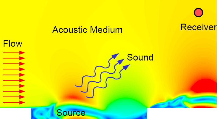
Therefore, we can consider the problem domain in two distinct layers: The flow field (governs sound source and generation through Navier-Stokes equations) and the acoustic field (governs sound propagation through the wave equation). This provides us with the opportunity to reduce our computational efforts significantly which opens up a wider variety of applications. Connection of the two segregated components (i.e. source and propagation) is achieved using an acoustic analogy. Generally the tensor term in the acoustic analogy represents the sound source calculated by the CFD simulation. Once CFD provides sound source information, the problem reduces to solving for sound propagation.

acoustics-analogy

ANSYS Fluent provides features to compute sound propagation using the Ffowcks-Williams and Hawkins (FHW) boundary element method (BEM), meaning it relies solely on unsteady pressure information at the domain boundary. Since this approach is much less computationally expensive, it provides considerable benefits to aerodynamic and hydrodynamic far-field noise scenarios as the CFD domain is only required to encompass the object generating the noise source (to calculate unsteady pressure fluctuations). ANSYS Fluent additionally offers coupling to other BEM/FEM acoustics tools, if real geometry effects, acoustic impedance or vibrating structures are to be considered.


Acoustics and Aeroacoustics training – Melbourne, August 10-11, 2015


acoustics-fea3

This advanced training will provide you with everything you need to confidently tackle acoustics and aeroacoustics problems, including:

  • A background on the theory of acoustics and aeroacoustics
  • Details on other important physics such as transient turbulence modelling
  • Details of the different types of FEA based acoustic simulations, including modal, harmonic, transient and vibro-acoustic analysis
  • Examine noise sources, perforated material and far field processing
  • Details of CFD-based aeroacoustics simulation techniques including direct CAA methods, FWH (segregated source/propagation methods, boundary element methods) and stochastic noise generation / broadband noise models
  • Overview of coupling Mechanical with CFD tools for aero-vibro-acoustics

SOURCE : COMPUTATIONALFLUIDDYNAMICS.COM

GLASS FIBERS AND FIBERGLASS

Selecting Composite Materials

Fiber reinforced composites are common, but do you know how to select the different types of fiber and resin used?rte

Comparing and Choosing Composite Materials

Composite materials are broadly defined as those in which a binder is reinforced with a strengthening material. Here we take a look at the pros and cons of the components: the resins and the fibers used to strengthen them.

Resins

Most modern composites share a common bond – almost literally. The binding resins – the chemical matrix in which the reinforcing fibers are embedded – are relatively few in number.

There are three main recipes: polyester, vinylester and epoxy. Various flavours of each are available, depending on whether they are strengthened with glass, carbon or aramid fibers, and the particular application. For example, high UV (sunlight) tolerance may be chemically engineered using additives.

Common Issues

The presence of volatile organic compounds(‘VOC’) is of concern both for health reasons and ‘greenhouse effect’ impact. Modern epoxies are VOC free, but polyester and vinylester compounds have high concentrations of VOC in the form of styrene. This means that fabrication using esters should take place in well ventilated space.

Curing

The epoxy compound is formed by mixing two different chemicals which react to form a ‘copolymer’. The curing rate is sensitive to temperature and the ratio of the two components, but curing is almost always assured. Some epoxy paste formulations will even cure underwater.


Polyester and vinylester by comparison, cure with the use of a peroxide catalyst (usually known as MEKP).

Vinylester is sensitive to temperature, and may not cure at all under certain conditions.

Water resistance

Epoxies are highly water resistant, with vinylesters also showing a high resistance.Polyester composites absorb water to a significant degree, and when used – say, in boat hulls – osmotic blistering occurs due to a reaction with water (hydrolysis) which results in chemical breakdown.

Insoluble pthallic acid crystals damage the GRP laminate and acetic acid is a by-product.

Chemical resistance

Epoxies are very stable chemically, and offer excellent resistance to chemical attack. Polyesters are moderately resistant at room temperatures to most common chemicals, but vinylesters offer much higher resistance, though falling short of the protection that epoxies afford. The resistance of polyesters and vinylesters falls quickly at higher temperatures. Vinylesters may be used to provide a barrier coating to protect polyester, particularly in the marine environment.

Shrinkage, Strength and Stiffness

Polyesters and vinylesters typically shrink by 7% on curing, but epoxies shrink less than 2% and where dimensional stability is important, then epoxies are much to be preferred.

Shrinkage can introduce stress into a structure, and designers much factor this in. Both for tensile strength and stiffness, polyester is lowest on the scale, with epoxy highest and vinylester just superior to polyester.

Adhesion

This is an important property when using composites. Adhesion has to be strong between the resin and the fiber strengthener. Vinylester is not the best in this respect.

Cost

Polyester is by far the cheapest of the three resin systems, much cheaper even than vinylester, weight for weight. Polyester is preferred for boats and bathtubs, but where strength/weight is important and budget less of an issue, then epoxies win – for example in motorsport and aerospace.

Fiber Types

There are three main families in use at present: glass fiber, carbon fiber and aramid fiber (more commonly known as Kevlar, a trademark of the DuPont Corporation).

Glass fiber is by far the cheapest and most widely used, and works well with all three resin types, but it is relatively heavy. Carbon fiber is much lighter, as are aramid fibers.

Glass fibers (either in chopped strand or woven cloth form) are most commonly used with a polyester resin, whereas carbon fiber, as a relatively high cost strengthener, is most usually combined with epoxy resins.

Adhesion

A resin has to ‘stick’ to the fiber strengthener, and it is important to select a resin/fiber combination (particularly with carbon and aramid fibers) so that there is good adhesion and the fibers are properly bonded within the resin.

Composite Comparisons

In general terms, Kevlar mechanical properties are good in strength (double that of glass fibers) but very poor in stiffness, whilst the glass composite is ten times as stiff and half the strength.

Kevlar is very expensive compared to glass, so it is used where higher strength and elongation is needed.

Both aramid composites and GRP are good at handling repeated flexing cycles (such as in a boat hull), but carbon fiber has an unpredictable life when subject to repeated flexing.

GRP requires a considerably ‘heavier’ construction to achieve the strength of carbon fiber. Aramid fibers offer equivalent strength to fiberglass at a much lower weight, although abrasion resistance is lower.

Summary

When choosing a composite, there are many factors to take into account. Many users of advanced composites – for example in the premium boat building industry – will combine all three composites to tailor engineering properties and weight distribution. In fact, we now have structures which are composites of composites.

SOURCE : COMPOSITE ABOUT.COM

QUAD COPTER CONTROLS

Quadcopter Controls

When learning how to fly a quadcopter, the controls will become your bread and butter.

They will become second nature once you know how they act individually and how they interact together to form a complete flying experience.

With any of these controls, the harder you push the stick, the stronger your quadcopter will move in either direction.

When you first start out, push the sticks very gently so the quadcopter performs slight movements.

As you get more comfortable, you can make sharper movements.

There are four main quadcopter controls:

  • Roll
  • Pitch
  • Yaw
  • Throttle
How-to-Fly-a-Quadcopter-Transmitter-Image.jpg
Simple Sketch of Roll, Pitch, Yaw and throttle on a transmitter (left image) and Quad copter (right image)

(Image source: Quadcopters Are Fun)

Let’s go through each of them.

Roll

Roll moves your quadcopter left or right. It’s done by pushing the right stick on your transmitter to the left or to the right.

It’s called “roll” because it literally rolls the quadcopter.

For example, as you push the right stick to the right, the quadcopter will angle diagonally downwards to the right.

How-to-Fly-a-Quadcopter-Image-Roll.png
Example of a Quad copter rolling left and right . Notice the tilt of the quad copter and the angle of the parameters.

(Image source: Best Quadcopter Spot)

Here, the bottom of the propellers will be facing to the left. This pushes air to the left, forcing the quadcopter to fly to the right.

The same thing happens when you push the stick to the left, except now the propellers will be pushing air to the right, forcing the copter to fly to the left.

Pitch

Pitch is done by pushing the right stick on your transmitter forwards or backwards. This will tilt the quadcopter, resulting in forwards or backwards movement.

How-to-Fly-a-Quadcopter-Image-Pitch.png
Example of a Quad copter pitching forwards and backwards. Note that this view is from the left side.

Yaw

Yaw was a little bit confusing for me in the beginning. Essentially, it rotates the quadcopter clockwise or counterclockwise.

This is done by pushing the left stick to the left or to the right.

Check out the video (Watch from 3:00 to 3:40 and pay attention to how he adjusts the sticks.)

Yaw is typically used at the same time as throttle during continuous flight. This allows the pilot to make circles and patterns. It also allows videographers and photographers to follow objects that might be changing directions.

Throttle

Throttle gives the propellers on your quadcopter enough power to get airborne. When flying, you will have the throttle engaged constantly.

Related: See the top 100 drone news sites of 2015

To engage the throttle, push the left stick forwards. To disengage, pull it backwards.

Make sure not to disengage completely until you’re a couple inches away from the ground. Otherwise, you might damage the quadcopter, and your training will be cut short.

Important note:

When the quadcopter is facing you (instead of facing away from you) the controls are all switched.

This makes intuitive sense…

  • Pushing the right stick to the right moves the quadcopter to the right (roll)
  • Pushing the right stick forward moves the quadcopter forward (pitch)
  • Pushing the right stick backward moves the quadcopter backward (pitch)
  • And so on.

So pay attention to that as you start changing directions. Always be thinking in terms of how the quadcopter will move, rather than how the copter is oriented towards you.

SOURCE : UAVCOACH.COM

Internal Combustion Engine Basics

Internal combustion engines provide outstanding drivability and durability, with more than 250 million highway transportation vehicles in the United States relying on them. Along with gasoline or diesel, they can also utilize renewable or alternative fuels (e.g., natural gas,propane).  They can also be combined with hybrid electric powertrains to increase fuel economy or plug-in hybrid electric systems to extend the range of plug-in hybrid electric vehicles.

internal-combustion-engines-ppt-6-638.jpg

HOW DOES AN INTERNAL COMBUSTION ENGINE WORK?

Combustion, also known as burning, is the basic chemical process of releasing energy from a fuel and air mixture.  In an internal combustion engine (ICE), the ignition and combustion of the fuel occurs within the engine itself. The engine then partially converts the energy from the combustion to work. The engine consists of a fixed cylinder and a moving piston. The expanding combustion gases push the piston, which in turn rotates the crankshaft and ultimately, through a system of gears in the powertrain, drives the vehicle’s wheels.

There are two kinds of internal combustion engines currently in production: the spark ignition gasoline engine and the compression ignition diesel engine. Most of these are four-stroke cycle engines, meaning four piston strokes are needed to complete a cycle. The cycle includes four distinct processes: intake, compression, combustion and power stroke, and exhaust.

Spark ignition gasoline and compression ignition diesel engines differ in how they supply and ignite the fuel.  In a spark ignition engine, the fuel is mixed with air and then inducted into the cylinder during the intake process. After the piston compresses the fuel-air mixture, the spark ignites it, causing combustion. The expansion of the combustion gases pushes the piston during the power stroke. In the diesel engine, only air is inducted into the engine and then compressed. Diesel engines then carry out combustion by spraying the fuel into the hot compressed air at a suitable, measured rate.

IMPROVING COMBUSTION ENGINES

Over the last 30 years, research and development has helped manufacturers reduce ICE emissions of criteria pollutants, such as nitrogen oxides (NOx) and particulate matter (PM) by more than 99% to comply with EPA emissions standards. Over the years, research has also led to improvements in ICE performance (horsepower and 0-60 mph acceleration time) and efficiency, helping manufacturers maintain or increase fuel economy.

Learn more about our advanced combustion engine research and development efforts focused on making internal combustion engines more energy efficient with minimal emissions.

SOURCE : ENERGY.GOV

TRICOPTER VS QUADCOPTER: EFFICIENCY, FLIGHT TIME, AND MORE

Tricopter Vs Quadcopter

The tricopter uses 3 motors and propeller propulsion units with servo which rotate one of the propellers to compensate for the adverse yaw. They were popular earlier when brushless motors and propeller units were scarce.

003.png

The copter suffers from lower performance and they don’t scale well to the larger sizes.

However, they still have some popularity for the small and light hobby use applications. The design is primarily outdated and therefore most people are not going for tricopters.

On the other hand

The quadcopter is the most popular design.

It has four propeller units and is also available in several sizes. Quadcopters are elegantly simpler in design and are hands on down the most popular layouts for various reasons. They are symmetrical and use the simplest operation principle for controlling pitch, roll, motion and yaw.

Varying the speed of each motor will provide you with hover capability and full rotation and 3D motion.

This also allows hover capability that most beginners 1st learn (or get familiar with when flying). They come in various sizes and layouts and are therefore capable of performing vital tasks beyond the flying.

The major problem with quadcopters is that single motor failure can result in a crash. A wider variety of materials and techniques may be applied to make a better quadcopter.

quadcopter.jpg

QUADCOPTERS ARE ALSO AVAILABLE IN SEVERAL POPULAR CONFIGURATIONS WHICH INCLUDE:

  • X with an X frame layout. The back and the front of the copter are usually between 2 propellers.
  • + With an x frame arm layout but with its front and back in line with one of its propellers.
  • H-model which has frame side arms running between motors on its sides. The arms are connected with a single or more frames at its middle.
  • The square model which has frame arms running between its motors and usually intermediary frame arms which support the central frame. There are variations which include some with motors laid out in a circle. They operate just like the X frame and they offer a better camera exposure in between the motors. The X frame design is much stronger and simple. Its natural symmetry also balances its flying forces better.

Whether you have a copter ready to fly (RTF) or you intending to purchase one, you can’t beat quadcopter’s simplicity. There is nothing complicated about quandcopter’s design, controls or construction. Its frame is a cross shape and all its motors bolt directly to the frame. Furthermore, it doesn’t need servos like those of a tricopter. Servos make it hard to stabilize a tricopter and to control it. They also limit you to the number of tricks to perform.

Tricopters are much cheaper than the quadcopters and especially when building your own copter. The major reason is that everything is less one – less one propeller, speed control and motor. Despite the harder controls and complex design, some people go for the copter due to its lower cost.

However

Pertaining to crash, both tri and quadcopters have questionable reliability. A quad has higher chances of surviving a crash compared to a tricopter. In case of a power system failure, the quadcopter’s mechanical simplicity gives it the edge it requires to survive. On the other side, the complicated tricopter’s servo construction creates vulnerability which highly decrease the chances of survival in case of a smash into a wall or the ground.


BREAKDOWN: WHAT’S THE DIFFERENCES BETWEEN THE A QUADCOPTER AND A TRICOPTER…


THE SIMILARITIES OF TRICOPTERS AND QUADCOPTERS


There are some similarities between quadcopters and tripcopters such as they are both motor copters. The traditional helicopters have two rotors, a tail rotor and the main rotor.

firmwares.jpg

The primary reason why you should switch from a helicopter to quadcopter is that you don’t have servos. The heli have three servos which control its main frame. They tilt in any direction and also control the blades pitch. This at times can be extremely complicated.

TRICOPTER VS QUADCOPTER, WHICH IS MORE EFFICIENT?

Size matters a lot. A quadcopter has a smaller size and therefore higher rotor lift to drag ratio which lowers the drone efficiency. How rotors interact with air affect the copters efficiency. Vicious forces dominate at higher speeds and smaller rotor length scaless. This means that smaller rotors are less efficient.

TRICOPTER VS QUADCOPTER FLIGHT TIME. WHAT ARE THE DIFFERENCES IN FLIGHT TIME?

The flight times of the two designs are considerably low and the highest ever recorded flight time for a drone is 3 hours. A flight time of quadcopter will generally last between 10 and 15 minutes while that of at tricopter may last for 21 minutes.

There are several conditions that affect the flight. For example, the flight will last for a shorter period on a windy day and during more maneuvering. The flight of a quadcopter can last up to 21 minutes during a calm day.

TRICOPTER VS QUADCOPTER, WHICH IS THE BETTER CHOICE FOR BEGINNERS?

There are many benefits and problems whether you choose to fly a tri or a quadcopter and at the end, neither of the two is better. It highly depends on your skills and what you enjoy. If you want more challenge, then you should try a tricopter.

Tricopters are cheaper and will offer you an exciting venture. On the other hand, quadcopters are much rugged and are less susceptible to breakage incase of a crush. The big question is how much time you would like to spend repairing the drone after a crash.

PROS & CONS OF TRICOPERS AND QUADCOPTERS

PROS AND CONS OF TRICOPTERS

Pros

  • One less motor
  • Less weight
  • Longer battery life and
  • Lower price

Cons

THE PROS AND CONS OF QUADCOPTERS

pros

  • They are simpler
  • Low repair cost incase of a crash
  • They can lift a larger weight
  • Higher chances of surviving a crash
  • They are available in many designs
  • They can move to any direction
  • Easier to fly

Cons

  • Not reliable
  • One motor failure can cause a crash

SOURCE : RCCRUNCH.COM

UAV PROPULSION

ESC

DYE-1012.jpg

An ESC (acronym for “Electronic Speed Controller“) is what allows the flight controller (covered in the next lesson) to control the speed and direction of a motor. The ESC must be able to handle the maximum current which the motor might consume, and be able to provide it at the right voltage. Most ESCs used in the hobby industry only allow the motor to rotate in one direction, though with the right firmware, they can operate in both directions.

Connectors

An ESC might initially be confusing because it has several wires exiting on two sides.

  • Power input: The two thick wires (normally black and red) are to obtain power from the power distribution board / harness which itself receives power directly from the main battery.
  • 3 bullet connectors: These pins are what connects to the three pins on the brushless motor. There are some standard sizes in the industry, but if you find the two are mismatched, you will need to replace one set.
  • 3-pin R/C servo connector: This connector accepts RC signals, but rather than requiring 5V on the red and black pins, most of the time an internal BEC provides 5V to power the electronics.

In certain instances, the manufacturer does not want to assume which connectors you are using, and leaves the wires for the motor connection and power input bare (they may provide bullet connectors in the packaging which you may or may not want/need and would have to solder onto the wires). The bullet connectors you received with the motors may also not match those of the ESC, so in this case, it’s simply best to replace one or the other. Your next question is obviously given three bullet connectors, which one plugs into which on the motor? As far as the connector for the power, this is entirely up to you – ideally you would use connectors to make the ESC easily removable in case of failure, or if you want to use it on a different project, but be sure that the positive on the ESC goes to the positive on the battery, and same for negative. In order to reverse the direction of rotation, swap any of two of the three connectors between the ESC and the brushless motor.

BEC

Most ESCs include what is called a “Battery Elimination Circuit” or BEC. This comes from the fact that historically, only one brushless motor was needed in a given RC vehicle, and rather than splitting hte battery, it would just need to be connected to the ESC, and the ESC would have an onboard voltage regulator to power the electronics.It is important to know the current which an ESC’s BEC can provide, though it is normally in the range of 1A or above and is almost always 5V.

In a multi-rotor, you need to connect four or more ESCs to the flight controller, but only one ESC is needed, and having power coming from multiple sources all being fed to the same lines can potentially cause issues. Since there is normally no way to deactivate a BEC on an ESC, it is best to remove the red wire and wrap it with electrical tape for all but one ESC. It is still important to leave the black (ground) wire in place for “common ground”.

Firmware

ESCs are not all equally good for use with multi-rotors. It is important to understand that before multi-rotors were around, that brushelss hobby motors were used primarily for RC car drives, airplane propellers and as primary motors in model helicopters. Most of these applications did not require very fast response time or rapid updating. An ESC equipped with SimonK or bheli firmware is able to react very fast (much higher frequency) to changes in input, which may mean the different between stable flight or a crash.

Power Distribution

Since each ESC is powered from the main battery, the main battery’s single connector must somehow be split amongst four ESCs. To do so, a power distribution board, or power distribution harness is used. This board (or cable) splits the main battery’s positive and negative terminals into four. It is important to note the type of connectors used on the battery, ESC and power distribution board may not all be the same, and it is best, whenever possible, to choose a “standard” connector (such as Deans) which is used throughout. Many inexpensive boards require soldering, as they do not want to assume you are using any specific connector. A very simply power distributor could involve a two input terminal block or soldering all positive connections together, and then all negative connections together..

SOURCE : ROBOTSHOP

UAV FRAMES & MATERIALS

UAV FRAME TYPES

Tricopter

Tricopter
  • Description: A UAV which has three arms, each connected to one motor. The front of the UAV tends to be between two of the arms (Y3). The angle between the arms can vary, but tends to be 120 degrees. In order to move, the rear motor normally needs to be able to rotate (using a normal RC servo motor) in order to counteract the gyroscopic effect of an uneven number of rotors, as well as to change the yaw angle. A Y4 is slightly different in that it uses two motors mounted on the rear arm, which takes care of any gyroscopic effects – no servo is therefore needed.
  • Advantages: Different “look” for a UAV. Flies more like an airplane in forward motion. Price is theoretically lowest among those described here since it uses the fewest number of brushless motor (and ESC).
  • Disadvantages: Since the copter is not symmetric, the design uses a normal RC servo to rotate the rear motor and as such, the design is less straightforward than many other multi-rotors. The rear arm is more complex since a servo needs to be mounted along the axis. Most, though not all flight controllers support this configuration.

Quadcopter

Quadcopter
  • Description: A “quadcopter” drone which has four arms, each connected to one motor. The front of the UAV tends to be between two arms (x configuration), but can also be along an arm (+ configuration).
  • Advantages: Most popular multi-rotor design, simplest construction and quite versatile. In the standard configuration, the arms / motors are symmetric about two axes. All flight controllers on the market can work with this multirotor design.
  • Disadvantages: There is no redundancy, so if there is a failure anywhere in the system, especially a motor or propeller, the craft is likely going to crash.

Hexacopter

Hexacopter
  • Description: A “hexacopter” has six arms, each connected to one motor. The front of the UAV tends to be between two arms, but can also be along one arm.
  • Advantages: It is easy to add two additional arms and motors to a quadcopter design; this increases the total thrust available, meaning the copter can lift more payload. Also, should a motor fail, there is still a chance the copter can land rather than crash. Hexacopters often use the same motor and support arm, making the system “modular”. Almost all flight controllers support this configuration.
  • Disadvantages: This design uses additional parts, so compared to a quadcopter which uses a minimum number of parts, the equivalent hexacopter using the same motors and propellers would be more expensive and larger. These additional motors and parts add weight to the copter, so in order to get the same flight time as a quadcopter, the batteryneeds to be larger (higher capacity) as well.

Y6

Y6 Hexacopter
  • Description: A Y6 design is a type of hexacopter but rather than six arms, it has three support arms, with a motorconnected to either side of the arm (for a total of six motors). Note that the propellers mounted to the underside still project the thrust downward.
  • Advantages: A Y6 design actually eliminates a support arm (as compared to a quadcopter), for a total of three. This means the copter can lift more payload as compared to a quadcopter, with fewer components than a normal hexacopter. A Y6 does not have the same issue as a Y3 as it eliminates the gyro effect using counter-rotating propellers. Also, should a motor fail, there is still a chance the copter can land rather than crash.
  • Disadvantages: This uses additional parts, so compared to a quadcopter which uses the same components, the equivalent hexacopter would be more expensive. Additional motors and parts add weigh to the copter, so in order to get the same flight time as a quadcopter, the battery needs to be larger (higher capacity) as well. The thrust obtained in a Y6 as opposed to normal hexacopter is slightly lower (based on experience), likely because the thrust from the top propeller is affected by the lower propeller. Not all flight controllers support this configuration.

Octocopter

Octocopter
  • Description: An octocopter has eight arms, each connected to one motor. The front of the UAV tends to be between two arms.
  • Advantages: More motors = more thrust, as well as increased redundancy.
  • Disadvantages: More motors = higher price and larger battery pack. When you reach this level. most users are looking at very heavy payloads such as DSLR cameras and heavy gimbal systems. Given the price of these systems, added redundancy is really important.

X8

X8 Octocopter
  • Description: An X8 design is still an octocopter, but has four support arms, each with a motor connected to either side of each arm, for a total of 8 motors.
  • Advantages: More motors = more thrust, as well as increased redundancy. Rather than using fewer yet more powerful motors, octocopters provide added redundancy in the event of a motor failure.
  • Disadvantages: More motors = higher price and larger battery pack. When you reach this level. most users are looking at very heavy payloads such as DSLR cameras and heavy gimbal systems.

UAV Size

UAVs come in a variety of different sizes, from “nano” which are smaller than the palm of your hand, to mega, which can only be transported in the bed of a truck. Although both very large and very small UAVs may get quite a bit of attention, they are not necessarily the most practical for hobbyists. For most users who are getting started in the field, a good size range which offers the most versatility and value is between 350mm to 700mm. This measurement represents the diameter of the largest circle which intersects all of the motors. Not only do parts for UAVs in this size range come in a variety of different prices, there is by far the greatest selection of products available.

Drone Size

Smaller UAVs are not necessarily less expensive than medium sized ones. This is largely due to the fact that the technology and time needed to produce small brushless motors or small brushless motor controllers is the same for small parts or for large ones. The prices for the additional electronics such as theflight controller, remote control, camera etc. tend not to change at all. The frame is normally one of the least expensive parts of a UAV, so although the frame for a small UAV may be half the price of a larger one, the overall price, with all parts needed, may still be very close.

UAV Materials / Construction

Below are the more common materials found in multi-rotor drones. This list does not include all possible materials which can be used and should be looked at as a guideline / opinion as to the use of each material to make the frame of a drone. Ideally the frame should be rigid with as minimal vibration transmission as possible.

Wood

If you want your frame to be as inexpensive as possible, wood is a great option, and will greatly reduce build time and additional parts required. Wood is fairly rigid and has been a proven material time and time again. Although the aesthetics may suffer, replacing a broken arm after a crash is relatively easy and “dirt cheap”. Painting the arm helps hide the fact that it’s wood. Ensure you use wood which is straight (no twisting or warping).

wood

Foam

Foam is rarely used as the sole material for the frame and there tends to be some form of inner skeleton or reinforcement structure. Foam can also be used strategically; as propeller guards, landing gear or even as dampening. There are also many different types of foam, and some variations are considerably stronger than others. Experimentation would be needed.

foam

Plastic

Most users can only access and work with plastic sheets (rather than 3D plastic shapes or objects). Plastic tends to flex and as such is not ideal. Used strategically (such as a cover or landing gear), plastic can be a great option. If you are considering 3D printing the frame, consider the time needed to print the part (versus buying a plastic frame kit), and how rigid the part will be in the air. 3D printing parts (or the entire frame) has so far been more successful on smaller quadcopters. Using plastic extrusions may also be an option for small and medium sized drones.

plastic

Aluminum

Aluminum comes in a variety of shapes and sizes; you can use sheet aluminum for body plates, or extruded aluminum for the support arms. Aluminum may not be as lightweight as carbon fiber or G10, but the price and durability can be quite attractive. Rather than cracking, aluminum tends to flex. Working with aluminum really only requires a saw and a drill; take the time to find the right cross section (lightweight and strong), and try to cut out any non-essential material.

Aluminum

G10

G10 (variation of fiberglass) is used as a less expensive option than carbon fiber, though the look and basic properties are almost identical. G10 is mostly available in sheet format and is used largely for top and bottom plates, while tubing in carbon fiber (as compared to G10) is usually not much more expensive and is often used for the arms. Unlike Carbon Fiber, G10 does not block RF signals.

g10

PCB

Printed Circuit Boards are essentially the same as fiberglass, but unlike Fiberglass, PCBs are always flat. Frames <600mm sometimes use PCB material for top and bottom plates, since the electrical connections integrated into the PCB can reduce parts (for example the power distribution board is often integrated into the bottom plate). Small quadcopter frames can be made entirely out of a single PCB and integrate all of the electronics.

pcb

Carbon Fiber

Carbon fiber is still the #1 sought-after building material due to its light weight and high strength. The process to manufacturer carbon fiber is still quite manual, meaning normally only straightforward shapes such as flat sheets and tubes are mass produced, while more complex 3D shapes are normally “one off”. Carbon fiber impedes RF signals, so be sure to take this into consideration when mounting electronics (especially antennas).

Carbon fiber

SOURCE : ROBOTSHOP

How Is Carbon Fiber Made?

The Manufacturing Process Of This Lightweight Material

Also called graphite fiber or carbon graphite, carbon fiberconsists of very thin strands of the element carbon. Carbon fibers have high tensile strength and are very strong for their size. In fact, carbon fiber might be the strongest material there is.

Each fiber is 5-10 microns in diameter. To give a sense of how small that is, one micron (um) is 0.000039 inches. One strand of spider web silk is usually between 3-8 microns.

Carbon fibers are twice as stiff as steel and five times as strong as steel, (per unit of weight). They also are highly chemically resistant and have high temperature tolerance with low thermal expansion.

Carbon fibers are important in engineering materials, aerospace, high performance vehicles, sporting equipment, and musical instruments–to name just a few of their uses.

Raw Materials

Carbon fiber is made from organic polymers, which consist of long strings of molecules held together by carbon atoms.  Most carbon fibers (about 90 percent) are made from the polyacrylonitrile (PAN) process. A small amount (about 10 percent) are manufactured from rayon or the petroleum pitch process.  Gases, liquids, and other materials used in the manufacturing process create specific effects, qualities, and grades of carbon fiber. The highest grade carbon fiber with the best modulus properties are used in demanding applications such as aerospace.

Carbon fiber manufacturers differ from one another in the combinations of raw materials they use. They usually treat their specific formulations as trade secrets.

Manufacturing Process

In the manufacturing process, the raw materials, which are called precursors, are drawn into long strands or fibers. The fibers are woven into fabric or combined with other materials that are filament wound or molded into desired shapes and sizes.

There are typically five segments in the manufacturing of carbon fibers from the PAN process.

These are:

  1. Spinning. PAN mixed with other ingredients and spun into fibers, which are washed and stretched.
  2. Stabilizing. Chemical alteration to stabilize bonding.
  3. Carbonizing. Stabilized fibers heated to very high temperature forming tightly bonded carbon crystals.
  4. Treating the Surface. Surface of fibers oxidized to improve bonding properties.
  5. Sizing. Fibers are coated and wound onto bobbins, which are loaded onto spinning machines that twist the fibers into different size yarns. Instead of being woven into fabrics, fibers may be formed into composites. To form composite materials, heat, pressure, or a vacuum binds fibers together with a plastic polymer.

Manufacturing Challenges

The manufacture of carbon fibers carries a number of challenges, including:

  • The need for more cost effective recovery and repair.
  • The surface treatment process must be carefully regulated to avoid creating pits that could result in defective fibers.
  • Close control required to ensure consistent quality.
  • Health and safety issues
  • Skin irritation
  • Breathing irritation
  • Arcing and shorts in electrical equipment because of the strong electro-conductivity of carbon fibers.

Future of Carbon Fiber

Because of its high tensile strength and lightweight, many consider carbon fiber to be the most significant manufacturing material of our generation. Carbon fiber may play an increasingly important role in areas such as:

  • Energy. Windmill blades, natural gas storage and transportation, fuel cells.
  • Automobiles. Currently used just for high performance vehicles, carbon fiber technology is moving into wider use.  In December 2011 General Motors announced that it is working on carbon fiber composites for mass production of automobiles.
  • Construction. Lightweight pre-cast concrete, earthquake protection.
  • Aircraft: Defense and commercial aircraft.  Unmanned aerial vehicles.
  • Oil exploration. Deep water drilling platforms, drill pipes.
  • Carbon nanotubes. Semiconductor materials, spacecraft, chemical sensors, and other uses.

In 2005, carbon fiber had a $90 million market size. Projections have the market expanding to $2 billion by 2015. To accomplish this, costs must be reduced and new applications targeted.

SOURCE : ABOUT.COM